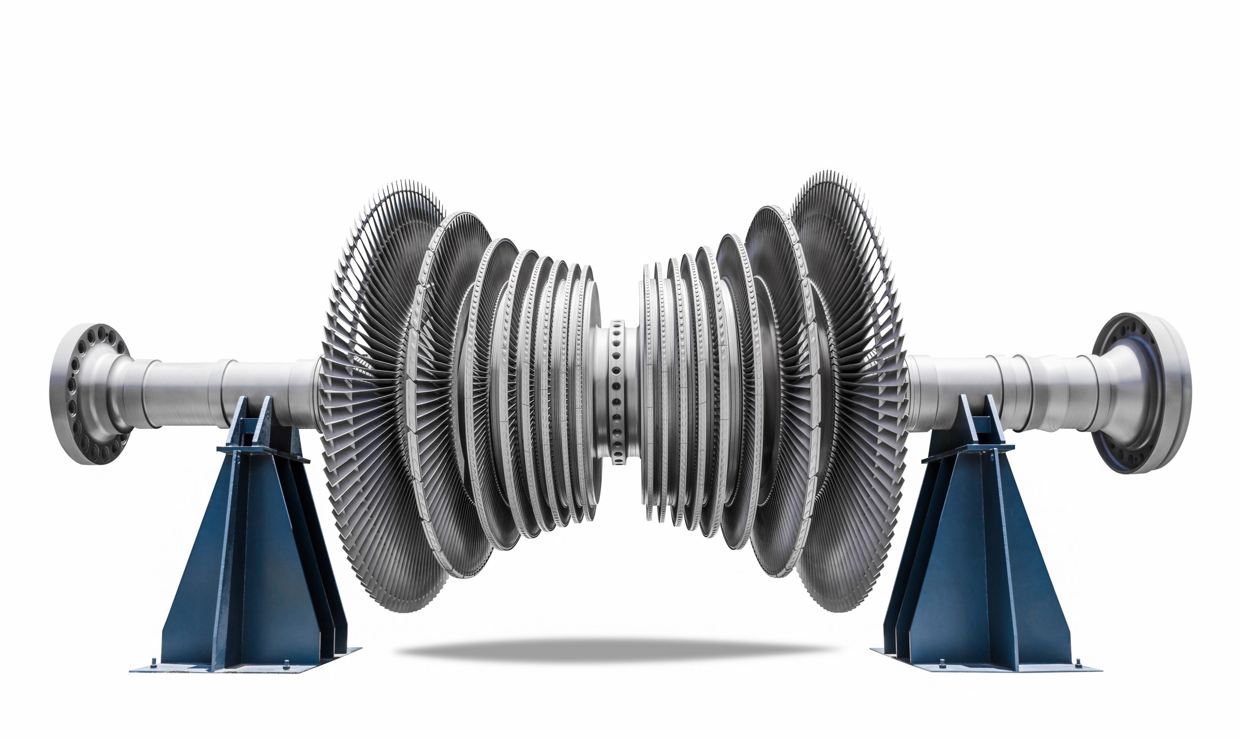
The steam turbine is a type of impulse reaction turbine which converts the thermal energy into mechanical energy. The history of this turbine goes back to the first century but Sir Charles Parsons invest the modern manifestation of the steam engine in 1884. This turbine has applications in transport mediums which use steam engines like trains and ships but mostly it is used to generate electricity.
This turbine uses steam to rotate the runner of the turbine. A boiler is used to convert water into steam. This steam is then passed through a nozzle to create a fast speed steam jet. The kinetic energy of this jet then moves the runner of turbine through the bucket shaped blades of the runner. The steam then moves to the condenser chamber which converts the steam back into water and water then goes back to the boiler. This cycle carries on to continuously rotating the runner of the turbine. The whole working scheme of the steam turbine is shown in figure 1.
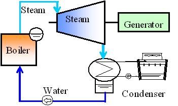
Figure 1: Working scheme of the whole system of steam turbine
The main steam turbine consists of rotors, blades, and shafts. The rotor and blades work in a sealed cylindrical shaped capsule to avoid leakage of steam as shown in figure 2. The steam jet enters the turbine from a small opening known as fed and leaves the turbine from broader opening known as exhaust. The speed of steam jet depend a lot o f on the expansion rate. Steam moves faster if the pressure difference between the feed and exhaust is kept higher. In early days, people used to generate the vacuum at the exhaust so that steam leaves the turbine at very low pressure so that more energy impart to the piston of the turbine.
On the contrary, Parsons kept a high pressure at the exhaust side of the turbine but still this pressure remain lower than the pressure of steam jet at the feed. This small change in pressure difference prevents steam to lose energy while moving through the rotor. Multiple sets of the rotor is used in this turbine. The size of these rotors increases from feed side to exhaust side as illustrated in figure 2.
Every rotor contains two set of blades; fixed blades and rotating blades. Fixed blades set the direction of steam so that it strikes the rotating blades with such an angle that transfer optimum amount of energy from steam to turbine. The steam leaves the first rotor and moves to the fixed blades of next rotor. This cycle continues until steam reaches the exhaust. In this way, maximum energy can be extracted from the steam without destroying the turbine.
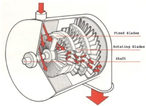
Figure 2: Schematic Diagram of Parson Type Steam Turbine
Steam moves very fast as compared to air and water, therefore, it is important to have an intelligent design to transfer this kinetic energy into mechanical energy without damaging the structure. The efficiency of this turbine is also higher than other gas turbines as steam jet move continuously unlike other gasses which enter the turbine in pulses.
https://global.kawasaki.com/en/energy/equipment/steam_turbines/
http://www.leander-project.homecall.co.uk/turbines.html

